Setup and Hold Time
The Fundamental Timing Parameters of Flip-Flops
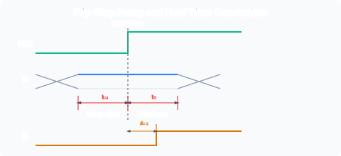
For a D flip-flop to sample data correctly, the D input must satisfy two timing constraints relative to the active clock edge:
Setup time (tsu): The minimum time for which the D input must be stable before the active clock edge. If D changes within tsu of the edge, the FF may not capture the correct value.
Hold time (th): The minimum time for which the D input must remain stable after the active clock edge. If D changes within th of the edge, the data may not be reliably stored.
Propagation delay (tp or tpcq): The time from the clock edge until the Q output reflects the sampled D value. Measured from the clock edge to the point where Q has stabilised at the new value.
These are visualised in the timing diagram:
Why These Constraints Exist
Within the flip-flop, the clock edge triggers a sequence of internal events: a transmission gate closes, trapping charge on a storage node. The D input must be stable:
- Before the edge, so that the correct voltage has time to charge the internal node through the input path. The setup time accounts for the RC delay of this charging.
- After the edge, because the transmission gate does not close instantaneously. If D changes while the gate is still partially open, the wrong value may leak through (“hold time violation”).
If either constraint is violated, the FF enters a metastable state (covered in /modules/digital-electronics/07-flip-flop-applications-and-timing/06-metastability/).
System-Level Timing: Setup Time Constraint
Consider a synchronous system where the output of FF0 passes through combinational logic to the input of FF1:
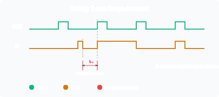
On the rising edge of CLK, FF0 outputs Q₀ after a delay tpcq (clock-to-Q propagation delay). This signal enters the combinational logic (CL), producing D₁ after a combinational delay tpd. D₁ is the input to FF1. For FF1 to sample correctly, D₁ must be stable at least tsu before the next clock edge. The analysis therefore tracks the longest possible path (worst-case maximum propagation delays):
Where:
- Tc is the clock period
- tpcq is the maximum clock-to-Q delay of FF0
- tpd is the maximum propagation delay through the combinational logic
- tsu is the setup time of FF1
This inequality determines the maximum clock frequency:
Worked Example: Maximum Clock Frequency
A system uses FFs with tpcq = 50 ps, tsu = 60 ps, th = 10 ps. The combinational logic between FFs has a worst-case delay tpd = 300 ps. What is the maximum clock frequency?
If the designer wants to clock at 3 GHz (Tc = 333 ps), the combinational logic must be redesigned such that:
This 77 ps reduction might require pipelining: inserting an additional register stage within the combinational logic to split the 300 ps path into two shorter paths.
Hold Time Constraint
While the setup constraint limits the maximum clock frequency, the hold time constraint is fundamentally different. The data at FF1’s D input must not change before th has elapsed after the clock edge. The analysis considers the shortest possible path (best-case minimum propagation delays, also called contamination delays):
Where tcd is the minimum delay from FF0’s clock edge to D₁ changing. This minimum is the sum of FF0’s minimum clock-to-Q delay (tccq, also called contamination delay) plus the minimum combinational logic delay:
Critical insight: hold time violations cannot be fixed by slowing the clock. Slowing the clock increases Tc, which helps setup but does nothing for hold: the data at D₁ still changes at the same time after the clock edge regardless of the clock period. If the minimum path delay is too small, you must add delay (buffer insertion) or redesign the circuit.
Why Hold Time Is Usually Easy to Satisfy
In modern FFs, the hold time is often designed to be 0 (or even negative, meaning D can change slightly before the edge). Additionally, the minimum clock-to-Q delay of a well-designed FF exceeds its own hold time (otherwise two FFs couldn’t be directly cascaded without violating hold). When th = 0, the hold constraint is trivially satisfied.
However, hold violations become a serious problem when clock skew is present (discussed in the next note /modules/digital-electronics/07-flip-flop-applications-and-timing/05-clock-skew/).
Contamination Delay Terminology
Some textbooks (notably Harris and Harris) distinguish:
- Propagation delay (tpd, tpcq): the maximum time for the output to settle.
- Contamination delay (tcd, tccq): the minimum time before the output begins to change.
The setup constraint uses maximum delays (worst case: how late can data arrive?). The hold constraint uses minimum delays (worst case: how early can data change?). This asymmetry is central to static timing analysis.