Clock Skew
What Is Clock Skew?
In an ideal synchronous system, the clock edge arrives at every flip-flop simultaneously. In a real circuit, the clock signal must be distributed through wires and buffers to reach thousands or millions of FFs. Differences in wire length, buffer delays, and capacitive loading cause the clock edge to arrive at different FFs at slightly different times. This variation is called clock skew (tskew).
Clock skew is measured as the time difference between the clock edge arriving at one FF and the same edge arriving at another FF on the same clock path. If the clock at FF1 lags behind the clock at FF0 by tskew, then:
Setup Time with Clock Skew
Consider FF0 (launching FF) and FF1 (receiving FF). The clock to FF1 is delayed by tskew relative to FF0:

FF0’s clock arrives first. After tpcq, Q₀ changes. After tpd through the combinational logic, D₁ settles. FF1’s clock arrives tskew later, giving the data an extra tskew to arrive. To check whether this helps or hurts, trace the timing carefully:
The setup constraint checks: from one clock edge at FF0 to the next clock edge at FF1, does D₁ arrive in time? If FF1’s clock is delayed by tskew relative to FF0’s clock, then the same clock edge that launches data from FF0 arrives at FF1 tskew later. But the data was launched at the previous edge (one period earlier). So the usable time is:
The clock skew reduces the available time for the combinational logic. The earlier constraint (without skew) gave tpd ≤ Tc - (tpcq + tsu). With skew:
For a fixed clock period, the maximum allowable combinational logic delay is reduced by tskew. If the system was designed to just meet timing without skew, introducing skew will cause setup violations. The remedy: increase the clock period (reduce frequency) or redesign the combinational logic to be faster.
Hold Time with Clock Skew: The Dangerous Case
If the clock at the launching FF (FF0) is delayed relative to the receiving FF (FF1), the data launched by FF0 changes later than expected. Meanwhile, FF1 captures data on its (earlier) clock edge. The data from the current clock edge at FF0 might arrive too early for FF1’s same clock edge:
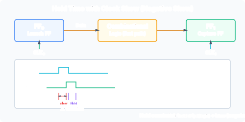
The hold constraint with skew becomes:
The minimum contamination delay through FF0 and the combinational logic must exceed the hold time plus the skew. Clock skew makes the hold constraint harder to satisfy.
Why Hold Violations from Skew Are Dangerous
Unlike setup violations, hold violations cannot be fixed by slowing the clock. The clock period does not appear in the hold inequality. If the minimum path delay is too small for the given skew, the only fixes are:
- Reduce the clock skew (improve clock distribution).
- Add delay buffers in the data path (increase tcd,logic).
- Use FFs with longer minimum clock-to-Q delay.
- Redesign to avoid very short combinational paths.
In practice, hold violations from skew are the most feared timing problem in chip design because they can appear after fabrication and cannot be patched by software (unlike setup, which can be mitigated by reducing clock frequency).
Clock Distribution Networks
To minimise skew, integrated circuits use carefully designed clock distribution networks:
H-trees: A recursive H-shaped pattern of wires that equalises the distance from the clock source to every leaf. Each branch has the same length, so the clock arrives simultaneously at all endpoints (in theory).
Clock grids: A mesh of horizontal and vertical clock wires covering the entire chip. Drivers feed the grid at multiple points. Low skew because the grid’s low impedance equalises arrival times, but high power consumption.
Clock buffers: Amplifiers placed along the distribution network to maintain signal integrity. Buffer delays must be matched across branches to avoid introducing skew.
In FPGAs, the clock distribution is built into the chip fabric with dedicated low-skew routing resources (global clock networks), simplifying the designer’s job.
Skew Sign Conventions
Skew is measured as the difference between the receiving clock and the launching clock. The sign of tskew matters for whether it helps or harms each constraint:
- Positive skew (receiving clock arrives after launching clock): hurts setup (less time for data to arrive) but helps hold (data has more time to stabilise).
- Negative skew (receiving clock arrives before launching clock): helps setup (more time) but hurts hold (data may arrive too early for the receiving FF’s earlier clock edge).
In a real chip, different pairs of FFs see different skew values. Static timing analysis must verify both setup and hold for all paths under all skew scenarios.
Relationship to Metastability
Clock skew interacts with metastability: if skew causes a setup or hold violation, the receiving FF can enter a metastable state. The analysis of metastability, synchronisers, and MTBF is covered in /modules/digital-electronics/07-flip-flop-applications-and-timing/06-metastability/.