Asynchronous Inputs
What Are Asynchronous Inputs?
In addition to the clock and data inputs, flip-flops typically provide asynchronous inputs: signals that override the clock and take effect immediately, regardless of the clock state. The two common asynchronous inputs are:
- Preset (PRE, sometimes called SET): forces Q = 1 immediately.
- Clear (CLR, sometimes called RESET): forces Q = 0 immediately.
They are called asynchronous because their effect does not depend on the clock: asserting PRE or CLR changes Q instantaneously (after a short propagation delay), even if no clock edge occurs.
Active-Low Convention
Asynchronous inputs are typically active-low: they are asserted when the signal is at logic 0, and are denoted with an overbar or bubble: PRĒ, CLR̄. The reason is historical and practical: active-low inputs can be driven by open-collector/open-drain outputs with a single pull-up resistor, allowing multiple sources to share a reset line (wired-AND). A typical D flip-flop with asynchronous inputs has the symbol:
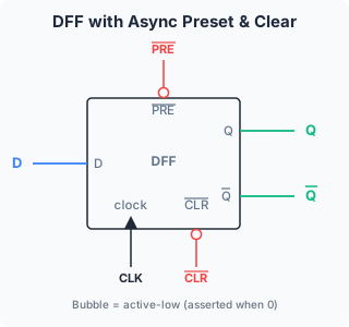
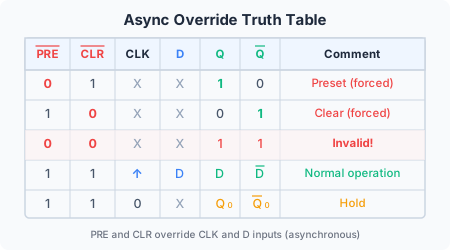
The truth table for a D-FF with active-low PRĒ and CLR̄:
| PRĒ | CLR̄ | CLK | D | Q’ | Q̄’ |
|---|---|---|---|---|---|
| 0 | 1 | X | X | 1 | 0 |
| 1 | 0 | X | X | 0 | 1 |
| 0 | 0 | X | X | 1 | 1 |
| 1 | 1 | ↑ | 0 | 0 | 1 |
| 1 | 1 | ↑ | 1 | 1 | 0 |
Where ↑ denotes a rising clock edge and X means “don’t care”. When both PRĒ and CLR̄ are asserted simultaneously, both Q and Q̄ go high (the same forbidden condition as the RS latch), so this combination must be avoided in normal operation.
Override Logic
The asynchronous inputs override the D input through additional gating in the FF’s internal feedback loop:
The CLR signal forces the output of the internal NOR gate to 0 regardless of the D path. The PRE signal forces it to 1. These override the clock-controlled path because they bypass the clock gating entirely.
Power-On Initialisation: The Primary Use Case
When a digital system powers up, the flip-flops come up in an unknown state: each FF may be 0 or 1 depending on random physical factors (manufacturing variation, thermal noise, exact supply ramp rate). For a finite state machine to start correctly, it must begin in a known reset state.
The standard solution: generate a power-on reset pulse. A simple RC (resistor-capacitor) circuit holds the CLR̄ line low for a few milliseconds after power-up while the capacitor charges, then releases it. During this time, all FFs are forced to Q = 0. When CLR̄ goes high, the system begins normal clocked operation from a known starting state.
This is exactly how the “start” state is loaded in the traffic light controller example in /modules/digital-electronics/08-synchronous-state-machines/04-fsm-worked-example-traffic-light/. On power-up, all FFs are cleared to 0, but the unused state 000 should transition to a valid state via the next-state logic (the “self-start” property). Alternatively, if the reset state is not the all-zeros state, PRĒ can be used on specific FFs to set the initial pattern.
Timing Considerations
Asynchronous inputs must still meet timing requirements:
Minimum pulse width. The PRĒ or CLR̄ pulse must be asserted for a minimum duration to guarantee that the FF’s internal nodes fully switch. This is specified in the FF’s datasheet (typically a few nanoseconds to tens of nanoseconds).
Recovery time. If an asynchronous input is deasserted too close to a clock edge, the FF may not have time to stabilise before the clock triggers. The recovery time is the minimum time between deasserting PRĒ/CLR̄ and the next active clock edge. Violating recovery time can cause the FF to go metastable or capture incorrect data.
Removal time. Similar to recovery time, but measured from the deassertion of the asynchronous input relative to the preceding clock edge if the FF was clocked while the async input was asserted.
These constraints mean that asynchronous inputs are not “free”: they must be controlled with careful attention to timing, particularly at the boundary between the asynchronous reset domain and the synchronous clock domain.
Comparison: Synchronous vs Asynchronous Reset
| Property | Synchronous Reset | Asynchronous Reset |
|---|---|---|
| Implementation | D input logic includes reset condition | Dedicated CLR̄ pin on FF |
| Timing | Must meet setup time (part of normal logic path) | Independent of clock |
| Clock needed? | Yes, reset takes effect on next edge | No, takes effect immediately |
| Power-up use | No (no clock on power-up) | Yes (forces known state before clock starts) |
| Glitch sensitivity | Low (glitches filtered by clock edge) | High (glitch on CLR̄ can reset system spuriously) |
| Static timing analysis | Included automatically | Requires special constraints |
Modern ASIC and FPGA designs often use a hybrid approach: an asynchronous reset for power-up initialisation, synchronised through a reset synchroniser (two FFs in series) to avoid glitch sensitivity and recovery time violations.