FSM Worked Example: Traffic Light Controller
The Specification
Design a synchronous Moore FSM to control a UK-style traffic light. The sequence is:
R (Red) → RA (Red + Amber) → G (Green) → A (Amber) → R …
Each state lasts one clock cycle by default (timer logic would extend this in practice, but we design the core sequencer). The FSM cycles indefinitely through these four states.
Step 1: State Diagram
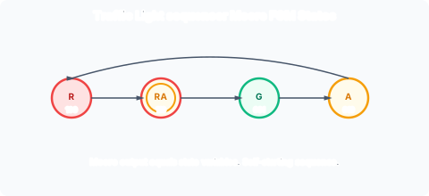
There are 4 states, so in theory 2 FFs would suffice (2² = 4). However, the clever design uses 3 FFs: one FF output directly drives each of the three lights (R, A, G). This eliminates the need for separate output combinational logic.
Step 2-3: Number of FFs and State Assignment
3 D-type FFs, labelled R, A, G (corresponding to the three lights). The encoding:
| State | R A G | Meaning |
|---|---|---|
| R | 1 0 0 | Red only |
| RA | 1 1 0 | Red + Amber |
| G | 0 0 1 | Green |
| A | 0 1 0 | Amber |
Unused states: 000, 011, 101, 111 (4 unused out of 8 possible).
Notice the output logic is trivial: the R light is lit when FF R = 1, the A light when FF A = 1, and the G light when FF G = 1. No output decoding needed. In the RA state (110), both R and A are 1, so both red and amber lights are on — correct for the UK sequence. The encoding naturally produces the right outputs for every state without any additional decoding logic.
Step 4-5: State Transition Table
| Current state | Next state |
|---|---|
| R A G | R’ A’ G’ |
| 1 0 0 | 1 1 0 |
| 1 1 0 | 0 0 1 |
| 0 0 1 | 0 1 0 |
| 0 1 0 | 1 0 0 |
| 0 0 0 | X X X |
| 0 1 1 | X X X |
| 1 0 1 | X X X |
| 1 1 1 | X X X |
Since we use D-FFs, D_R = R’, D_A = A’, D_G = G’.
Step 6-7: K-Map Minimisation
For D_R (next state of R FF):
(Note: the entry at corresponds to state (RA), which transitions to (G), so its next-state value for is . All other used states match their respective next-state values, and unused states are don’t-cares marked as ).
The 1 entries: (R,A,G) = 100 → 110 (R’=1), 110 → 001 (R’=0), 010 → 100 (R’=1). The 0 entry: 001 → 010 (R’=0).
From the K-map:
D_R is the XOR of R and A. When R=0, A=1 (Amber state): D_R = 1 → next state has R=1 (Red state). When R=1, A=0 (Red state): D_R = 1 → next state has R=1 (RA state). When R=1, A=1 (RA state): D_R = 0 → next state has R=0 (Green). When R=0, A=0 (Green): D_R = 0 → R stays 0.
So: R toggles when A=0, and R=1 when A=1 (until A toggles again). The XOR captures this.
For D_A:
By inspection of the table: A’ = 1 when RAG = 100 (next RA, A’=1), A’ = 0 when RAG = 110 (next G, A’=0), A’ = 1 when RAG = 001 (next A, A’=1), A’ = 0 when RAG = 010 (next R, A’=0). In every case, D_A equals the complement of the current A value: A toggles every cycle.
For D_G:
By inspection: G’ = 0 when RAG = 100 (next RA), 1 when RAG = 110 (next G), 0 when RAG = 001 (next A), 0 when RAG = 010 (next R). This is D_G = 1 only when R=1 and A=1. So:
Summary of Next-State Equations
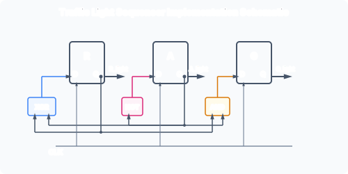
These are remarkably simple: one XOR, one NOT, one AND. Two of the three D inputs require only a single gate each.
Step 8: Schematic
Step 9: Unused State Analysis (Self-Start Check)
Plug each unused state into the next-state equations:
- 000: D_R = 0⊕0 = 0, D_A = NOT 0 = 1, D_G = 0·0 = 0 → next state = 010 (Amber). Valid!
- 011: D_R = 0⊕1 = 1, D_A = NOT 1 = 0, D_G = 0·1 = 0 → next state = 100 (Red). Valid!
- 101: D_R = 1⊕0 = 1, D_A = NOT 0 = 1, D_G = 1·0 = 0 → next state = 110 (RA). Valid!
- 111: D_R = 1⊕1 = 0, D_A = NOT 1 = 0, D_G = 1·1 = 1 → next state = 001 (Green). Valid!
All unused states transition directly to a valid used state. The machine is self-starting: regardless of its power-up state, it reaches the main cycle within one clock cycle. No asynchronous reset is strictly needed for correct operation, though one is still recommended for deterministic initial behaviour.
Why the XOR Pattern Emerges
The traffic light sequence is a ring: R → RA → G → A → R. The encoding (100 → 110 → 001 → 010 → 100) produces a pattern where:
- A toggles on every clock edge (D_A = Ā).
- R toggles only when A is not toggling (D_R = R ⊕ A, which means R toggles when A=0, holds when A=1).
- G is 1 only at the one point in the cycle where both R and A coincide (R·A = 1 in the RA state, which transitions to G).
This simplicity is a consequence of the clever state assignment. A naive sequential assignment (00, 01, 10, 11) would have produced much more complex equations.
Extended Version (6 States)
The course also presents a 6-state version with extended R and G periods, using a 4th FF (S) that toggles to create the extra dwell time. With 4 FFs, the equations become:
The additional FF S simply toggles, creating a two-cycle dwell in the R and G states. The pattern: in the R states (1000 and 1001), the extra S bit holds the machine in R for two cycles. Similarly for G (0010 and 0011). The equations are only slightly more complex than the 4-state version.