Elimination of Redundant States
Why minimise the state count?
When you design a finite state machine by hand it is easy to introduce states that do more work than necessary. Two states may behave identically from the outside, or one state may be unreachable entirely. Carrying these redundant states around has three costs:
- More flip-flops. The number of flip-flops needed to encode states is . Reducing 8 states to 6 states saves no flip-flops, but reducing 9 states to 8 states saves a whole flip-flop.
- More complex next-state logic. With fewer states there are more unused encodings, which become “don’t care” entries in the Karnaugh maps for the next-state logic. Don’t cares are the fuel that Boolean simplification runs on.
- More human error. A state diagram with redundant states is harder to reason about and easier to wire incorrectly.
The aim of state minimisation is to take a state table that is correct but bloated and produce a smaller state table that behaves identically: for every possible input sequence, the original machine and the reduced machine produce the same output sequence.
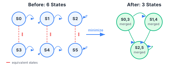
A subtlety: minimising a Moore machine is not always possible without adding outputs. In particular, a Mealy machine that has been naively converted to Moore form will usually have many apparently redundant states that cannot be removed in the Moore representation, because each Moore state can only emit one output value. Where this matters in practice (Examples Paper 2, Q4) the Mealy form is preferred.
The two techniques
The course teaches two techniques, in increasing order of power:
- Row matching. Look for two rows whose next-state entries and outputs are literally identical under every input. If the rows are identical, the two states are equivalent and one can be removed. This is fast and intuitive but only catches redundant states whose next states already match line for line.
- State equivalence via the implication table. A more general method that catches cases where two states have different next-state entries that are themselves equivalent. This is what you need when row matching fails.
Both methods operate on the state table. For a Mealy machine the output is a function of (state, input), so the table has separate output columns for each input value. For a Moore machine the output depends only on the state, so the output is a single column.
The two techniques are covered in the next two notes:
A note on unreachable states
State minimisation as taught here assumes you have already drawn a state diagram and converted it to a state table. A state that no transition ever reaches from the reset state is also redundant, but you handle those differently: by walking the diagram from the reset state and crossing out any state you never visit. This is a separate cleanup step, not part of row matching or the implication table.