Ripple Counters
What Is a Ripple Counter?
A ripple counter (also called an asynchronous counter) is the simplest way to build a binary counter. It consists of a chain of T-type flip-flops operating in toggle mode (T = 1 permanently), where each FF is clocked by the output of the previous stage rather than by the system clock.
Structure of an n-bit Ripple Counter
For a 3-bit ripple counter, three negative-edge-triggered T flip-flops (or JK FFs with J = K = 1) are connected as follows:

- FF0: T0 = 1 (toggle every clock), clocked by CLK.
- FF1: T1 = 1, clocked by Q0 (the output of FF0).
- FF2: T2 = 1, clocked by Q1 (the output of FF1).
The outputs Q2 Q1 Q0 form a 3-bit binary count.
Operation: How the Ripple Propagates
A T flip-flop with T = 1 toggles on each active clock edge. With negative-edge triggering, each FF toggles when its clock input falls from 1 to 0.
Trace the count sequence:
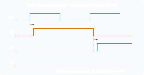
- FF0 (Q0) toggles on every falling edge of CLK. Q0 has half the frequency of CLK.
- FF1 (Q1) toggles on every falling edge of Q0: that is, every time Q0 goes from 1 to 0, which happens once every two CLK cycles.
- FF2 (Q2) toggles on every falling edge of Q1: once every four CLK cycles.
The binary count Q2Q1Q0 increments from 000 through 111 and wraps back to 000.
Each output has half the frequency of the previous one. This is why counters are often called dividers: Q0 divides the clock by 2, Q1 divides by 4, Q2 divides by 8. A divide-by-m counter can be built by detecting count m and resetting the FFs.
The Critical Problem: Ripple Delay
FF0 changes almost immediately after the CLK edge (after FF0’s propagation delay, tp_CO). But FF1 does not see the change until Q0 transitions, and then FF1 takes its own tp_CO to respond. The total delay from the CLK edge to Q2 settling is:
For an n-bit counter, the most significant bit settles n propagation delays after the clock edge. During this ripple time, intermediate count values appear at the outputs. For example, when the count transitions from 011 to 100:
- Q0 falls (011 → 010): correct halfway.
- Q1 falls (010 → 000): incorrect value appears.
- Q2 rises (000 → 100): finally correct.
The sequence 011 → 010 → 000 → 100 shows glitching values at the counter output. If combinational logic reads the counter during the ripple time, it will see incorrect counts and produce erroneous outputs.
Maximum Clock Frequency
The total ripple delay limits the maximum counting speed. If the clock period is shorter than the time needed for all FFs to settle, the counter will miscount. For an n-bit counter:
For example, with tp_CO = 10 ns and n = 8, fmax = 12.5 MHz. Adding more bits reduces the maximum frequency proportionally.
In contrast, a synchronous counter has a maximum frequency limited by the propagation delay of a single FF plus the combinational logic for the next-state equations, not by n times the FF delay.
When Ripple Counters Are Acceptable
Ripple counters ARE suitable for:
- Simple event counting where only the final count matters and it is read well after the ripple has settled.
- Frequency division where each output is used independently as a slower clock.
- Low-speed applications where glitching on intermediate bits is irrelevant.
They are NOT suitable for:
- Driving combinational logic that reads the counter value.
- Systems where the count must be valid at all times.
- High-speed designs where the ripple delay exceeds the clock period.
Non-Power-of-2 Counters
A ripple counter that counts modulo m (where m is not a power of 2) can be built by detecting the count of m and using an asynchronous clear to reset the FFs. For a BCD counter (0-9, modulo 10):
- Use a 4-bit ripple counter (counts 0-15).
- Detect binary 1010 (decimal 10) with an AND gate.
- Feed the AND output to the asynchronous CLR̄ inputs of all FFs.
When the count reaches 1010, the AND gate briefly asserts CLR̄, forcing all FFs to 0. The counter then resumes counting from 0. The count 1010 exists only for a glitch-width pulse before being cleared, so the effective sequence is 0000 → 0001 → … → 1001 → 0000.
Relationship to Synchronous Counters
Ripple counters violate the synchronous design principle: not all FFs share the same clock. The synchronous counter, covered in /modules/digital-electronics/07-flip-flop-applications-and-timing/02-synchronous-counters/, eliminates the ripple problem at the cost of more complex combinational logic.