Hardware Description Language Design Flow
Writing circuits as text
Designing an FPGA by drawing a schematic for every CLB is impractical once a design passes a few dozen logic elements. In practice the design is written in a Hardware Description Language (HDL), of which Verilog and VHDL are the two main dialects used in industry and teaching. An HDL file does not describe a sequential program the way a Python file does; it describes the structure and behaviour of hardware that will end up wired together on the chip.
There are two main flavours of HDL description, and a real design uses both:
- Behavioural descriptions say what the hardware does (for example, “this block adds two 8-bit numbers and registers the result on the rising edge of
clk”). The tools infer the adder, the registers and the routing. - Structural descriptions say how the hardware is wired (for example, instantiating an AND gate and connecting its inputs and outputs to named signals). Structural code is closer to a netlist and is used when you need explicit control over the hardware you instantiate.
The synthesis, place and route flow
Once you have HDL, the path from source to a configured FPGA goes through several stages, each of which is a heavy piece of vendor-supplied software.
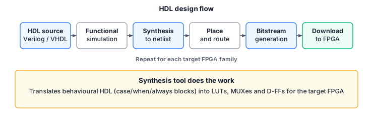
- Functional simulation. Before anything is built, a simulator (such as ModelSim, Icarus Verilog or the vendor’s own) exercises the HDL against a testbench. This catches logic errors cheaply. Getting the behaviour right here means you are not debugging real hardware later.
- Synthesis. The synthesis tool reads the HDL and translates the behavioural constructs into a netlist of gates, LUTs, multiplexers and flip-flops. This is where “always blocks” become D-FFs, “if” statements become multiplexers, and arithmetic operators become adders. The tool uses the target FPGA’s technology library so it picks real primitives: LUTs of the right input width, carry chains, and so on.
- Place and route. The tool takes the netlist and decides which physical CLB each LUT and D-FF lives in (placement) and which routing channels connect them (routing). This is a constrained optimisation problem; the tool tries to minimise delay and routing congestion while meeting timing constraints.
- Bitstream generation. Once place and route finish, the tool produces a bitstream: a binary file containing the LUT truth tables, the multiplexer select signals, the switch matrix connections and the IOB configuration.
- Download. The bitstream is written into the FPGA’s configuration SRAM, either directly from a host computer (often over USB-JTAG) or from an attached EEPROM at power-up.
Why this matters
Once a design is in HDL the same RTL can target different physical parts by re-running synthesis, place and route for each device. The logic does not change when the FPGA family changes, only the target library and the constraints. This is a huge step up from GALs, where the AND/OR plane structure forced the design down to product terms specific to that device.
Behavioural HDL also lets you raise the level of abstraction. You describe a state machine as a case statement on the state register inside a clocked always block, and the synthesis tool worries about flipping inputs into the next-state LUTs and registering the state in the D-FFs of the CLBs. The HDL is closer to a state diagram than to a schematic, which is the point.
Constraints and why timing is hard
FPGA timing is governed by the clock period and the longest path through the routed logic. After place and route, the tool reports the worst-case path delay. If that delay exceeds the clock period, the design will not meet timing, and you need to either:
- retell synthesis to optimise harder for speed,
- pipeline the offending path by adding a register stage (splitting a long combinational path in half),
- or manually move critical logic in the floorplan to use dedicated resources (DSP blocks, block RAM, carry chains).
None of this is examined in detail in Digital Electronics. The point you should take away is that HDL is descriptive hardware, the synthesis flow turns it into a programming of a real chip, and getting the design to meet timing is what place and route actually has to guarantee.
See also: