Moore vs Mealy Machines
Finite State Machines: Formal Definition
A Finite State Machine (FSM) is a deterministic circuit that produces outputs which depend on its internal state and external inputs. An FSM is defined by:
- A finite set of states (shown as circles on the state diagram).
- A set of inputs (external stimuli, labelled as arcs on the state diagram).
- A set of outputs (results from the FSM).
- A state transition function that, given the current state and current inputs, determines the next state.
- An output function that determines the current outputs.
There are two distinct types of FSM, classified by how the outputs are generated: Moore and Mealy.
Moore Machine
In a Moore machine, the outputs depend only on the current state. Outputs change synchronously with state transitions (i.e., on clock edges). The block diagram:
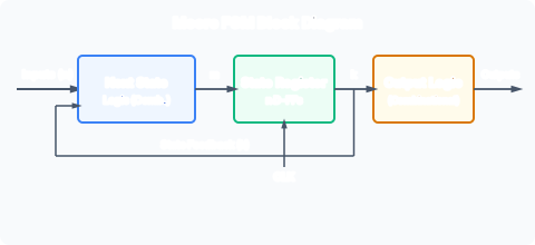
The next-state logic is combinational: it computes the next state from the current state and inputs. The output logic is also combinational, taking only the current state as input. If the state encoding is chosen to make the FF outputs directly usable as the system outputs (as in the traffic light controller), the output logic may be trivial or absent.
Mealy Machine
In a Mealy machine, the outputs depend on both the current state AND the current inputs. The block diagram:
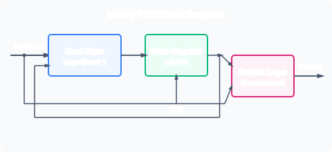
Notice the output logic takes inputs directly from both the current state AND the external inputs. This means Mealy outputs can change asynchronously with input changes, even mid-cycle, whereas Moore outputs only change on clock edges.
Comparison: Moore vs Mealy
| Property | Moore | Mealy |
|---|---|---|
| Output depends on | Current state only | Current state + inputs |
| Output timing | Synchronous to clock | Can change asynchronously with inputs |
| Output glitches | Glitch-free (from registered state) | Potentially glitchy (combinational path from inputs) |
| Number of states | Typically more | Typically fewer for same function |
| State diagram notation | Outputs inside state circles | Outputs on transition arcs |
| Conversion | Moore → Mealy: trivial | Mealy → Moore: may need more states |
State Diagram Notation
The diagrams for the two types use different conventions.
Moore notation: outputs are written inside the state circles, separated from the state name or binary encoding. Transitions are labelled with the input condition only:
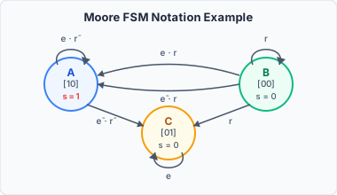
Here s₁s₀ = 10 means state A, 00 means state B, 01 means state C. Output s is derived from s₁.
Mealy notation: transitions are labelled “inputs/output”:
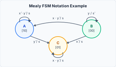
The label “x·ȳ/s” means: if inputs x = 1 and y = 0, the transition is taken and output s = 1. Outputs appear on the arcs, not in the state circles.
Example: Sequence Detector “01” (Overlapping)
Consider a machine that outputs 1 whenever the last two input bits were 01 (with overlap: “001” produces an output on the second 0→1 transition).
Moore implementation (3 states):
- S0: reset / last input was 0 (saw no progress) → output 0
- S1: saw “0” → output 0
- S2: saw “01” → output 1
Mealy implementation (2 states):
- S0: nothing useful seen so far
- S1: just saw a 0
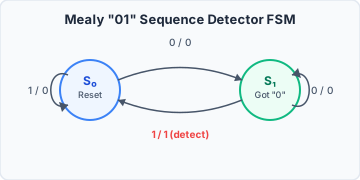
In the Mealy machine, output 1 occurs on the arc from S1 to S0 (input = 0). This requires only 2 states versus 3 for Moore, and the output appears as soon as the input changes (combinational delay), whereas the Moore output waits for the next clock edge.
Conversion Between Types
Moore → Mealy: Simply move the output from inside the state circle to all incoming transitions. The outputs become associated with the arcs. This is always possible without adding states.
Mealy → Moore: More involved. Since Mealy outputs can differ depending on the input that caused a transition to a state, a single Moore state cannot represent both. The state must be split: each distinct input/output combination arriving at a Mealy state becomes a separate Moore state. This can increase the state count.
Why Moore Is Preferred for Synthesis
Moore machines are generally preferred in hardware synthesis because:
- Outputs come from clocked registers: guaranteed glitch-free.
- Timing analysis is simpler: output timing is always relative to the clock edge.
- Modern synthesis tools handle the state explosion of Moore vs Mealy automatically.
Mealy machines are used when:
- Minimising the number of states is critical (e.g., in very simple controllers).
- An output must respond to an input within the same clock cycle (though output glitches must be managed).
Relevance to the Course
The traffic light controller in /modules/digital-electronics/08-synchronous-state-machines/04-fsm-worked-example-traffic-light/ is a Moore machine: the outputs (R, A, G lights) depend only on the current state. The Tripos example in /modules/digital-electronics/08-synchronous-state-machines/05-fsm-tripos-example/ is also Moore: the output s depends only on the current state. The row matching example in /modules/digital-electronics/09-state-machine-optimisation/02-row-matching/ involves a Mealy machine (outputs on arcs).