Decoders
Definition
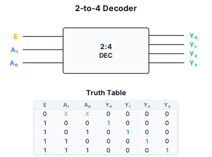
A decoder is a combinational circuit with n inputs and 2^n outputs. For each input combination, exactly one output is asserted (logic 1); all others are de-asserted (logic 0). It is sometimes called an n-to-2^n decoder or binary decoder.
2:4 decoder
A 2:4 decoder has inputs A, B (where A is the more significant bit) and outputs D0...D3:
| A | B | D0 | D1 | D2 | D3 |
|---|---|---|---|---|---|
| 0 | 0 | 1 | 0 | 0 | 0 |
| 0 | 1 | 0 | 1 | 0 | 0 |
| 1 | 0 | 0 | 0 | 1 | 0 |
| 1 | 1 | 0 | 0 | 0 | 1 |
Each output Di is the minterm of the inputs: D0 = Ā · B̄, D1 = Ā · B, D2 = A · B̄, D3 = A · B.
Implementation
A decoder is built from AND gates (one per output) and inverters (to generate complemented versions of the inputs). A 3:8 decoder requires three inverters and eight 3-input AND gates. An enable input (EN) gates all outputs: when EN = 0, all outputs are 0; when EN = 1, the decoder operates normally. Enable inputs allow decoders to be cascaded.
Building logic with decoders
A decoder generates all minterms of the input variables. Since any Boolean function can be expressed in DNF as the OR of its minterms, a decoder plus an OR gate implements any function:
- Feed the function’s inputs to the decoder.
- OR together the decoder outputs corresponding to minterms where the function is 1.
Example: Implement the majority function f = a·b + a·c + b·c using a 3:8 decoder. The minterms where f = 1 are m3 (011), m5 (101), m6 (110), m7 (111). OR together decoder outputs D3, D5, D6, D7.
Advantages of this approach:
- Regular structure: the decoder provides all minterms as an array.
- Fixed, predictable delay: one decoder delay + one OR gate delay, regardless of function complexity.
- Easy to modify: to change the function, just add/remove connections to the OR gate.
Disadvantages:
- Exponential growth: n inputs require 2^n AND gates. Beyond 5-6 inputs, decoders become impractical.
- Does not exploit don’t-care conditions or function-specific structure.
Decoder and MUX equivalence
A decoder followed by an OR gate is functionally equivalent to a ROM or a MUX-based LUT with hardwired data inputs. The decoder generates the address space; the OR gate selects the outputs. This equivalence underpins the implementation of logic in memories, PLAs, and FPGA LUTs.
Enable and cascading
Decoders with enable inputs can be cascaded to build larger decoders. For example, two 2:4 decoders with enables can form a 3:8 decoder: use the third address bit to select which decoder is enabled (via the EN input), while the first two bits feed both decoders’ address inputs.
Real-world use
Decoders are used extensively in digital systems:
- Memory address decoding: selecting which memory chip or peripheral responds to a given address range.
- Instruction decoding: the opcode field selects which control signals to activate.
- Seven-segment display drivers: a 4:16 decoder (BCD to decimal) feeds a display.
- State machine outputs: in one-hot encoded FSMs, the state register is essentially a decoder.