Multiplexers and Demultiplexers
Multiplexer (MUX)
A multiplexer is a combinational circuit that selects one of several data inputs and routes it to a single output. The selection is controlled by select lines.
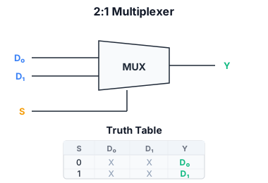
A 2:1 MUX has two data inputs (x, z), one select line (a), and one output (f):
| a | f |
|---|---|
| 0 | x |
| 1 | z |
Boolean expression: f = ā · x + a · z. The gate-level implementation is two AND gates gated by ā and a, feeding an OR gate.
A 4:1 MUX has four data inputs (D0…D3), two select lines (S1, S0), and one output. Each data input is gated by one minterm of the select lines:
An n:1 MUX requires ⌈log2 n⌉ select lines.
Building larger MUXes
A 4:1 MUX can be built from three 2:1 MUXes: two in the first level select between pairs of inputs (using S0), and a third selects between the two intermediate results (using S1). This hierarchical structure is commonly used in practice.
An 8:1 MUX uses seven 2:1 MUXes: four in level 1 (select S0), two in level 2 (select S1), one in level 3 (select S2).
MUX as universal logic
A 2^n:1 MUX can implement any n-variable Boolean function. The idea: the select lines are the function inputs, and the data inputs are hardwired to 0 or 1 according to the truth table.
Example: Implement f = a ⊕ b using a 4:1 MUX. Connect a, b to select lines S1, S0. The truth table of XOR is: a,b = 00 → 0, 01 → 1, 10 → 1, 11 → 0. So hardwire: D0 = 0, D1 = 1, D2 = 1, D3 = 0. At any time, the MUX selects the output matching the current input combination.
This is essentially a lookup table (LUT) implementation — the same principle used in FPGAs, where every LUT is a small MUX-based ROM.
Shannon expansion: Any function f(a, b, c) can be written as f = ā · f(0, b, c) + a · f(1, b, c). The sub-functions f(0,b,c) and f(1,b,c) can themselves be implemented with smaller MUXes. This recursive decomposition is the basis for MUX-based logic synthesis.
Demultiplexer (DEMUX)
A demultiplexer performs the opposite function: it routes a single input to one of several outputs based on select lines. A 1:2 DEMUX has one data input, one select line, and two outputs: when S = 0, the input goes to output 0 (output 1 = 0); when S = 1, the input goes to output 1 (output 0 = 0).
A 1:4 DEMUX has two select lines and four outputs. The unselected outputs are 0. A DEMUX is essentially a decoder (see the decoder notes) with the data input gating all outputs — but conceptually they are distinct components.
Decoder vs demultiplexer
A decoder has n inputs and 2^n outputs; exactly one output is 1 (the one selected by the input code). It has no data input.
A demultiplexer has n select inputs plus a data input, and 2^n outputs; the selected output equals the data input, all others are 0. A decoder can be turned into a demultiplexer by using an enable input as the data input.