Pipelined Processor
The idea: temporal parallelism
A pipelined processor is like an assembly line. Instead of one instruction going through all five stages before the next begins, multiple instructions are in flight simultaneously, each in a different stage. This is temporal parallelism: overlapping the execution of sequential instructions without duplicating hardware.
Five pipeline stages
A single-cycle processor’s work is naturally divided into five logical stages:
- Fetch (F): Read instruction from memory at address PC.
- Decode (D): Parse fields, read source registers from register file.
- Execute (E): ALU performs the operation or computes memory address.
- Memory (M): Access data memory (read for LOAD, write for STORE; idle for R-type).
- Writeback (W): Write result to destination register.
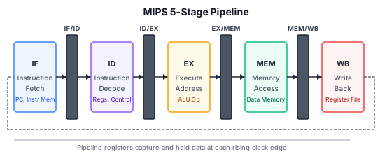
In a single-cycle processor, all five happen in one long clock cycle. In a pipelined processor, each stage becomes a separate pipeline stage with its own pipeline register between stages to hold intermediate results.
Throughput improvement
In the single-cycle processor, one instruction completes every clock cycle, but each clock cycle takes the full instruction time. In a 5-stage pipeline:
- Each clock cycle, a new instruction enters the pipeline (at the Fetch stage).
- Each clock cycle, one instruction completes (exits the Writeback stage).
- The clock period is determined by the slowest pipeline stage, not the whole instruction. Since each stage is approximately 1/5 of the work, the clock can be about 5 times faster.
- Throughput: ideally one instruction per clock cycle, with a clock 5× faster → 5× throughput improvement.
The latency of any single instruction is still 5 cycles (from fetch to writeback). But the throughput (instructions per second) is multiplied by the number of pipeline stages.
Timing diagram
Cycle-by-cycle view with instructions I1, I2, I3, I4, I5 entering the 5-stage pipeline:
| Cycle | Stage 1 (F) | Stage 2 (D) | Stage 3 (E) | Stage 4 (M) | Stage 5 (W) |
|---|---|---|---|---|---|
| 1 | I1 | — | — | — | — |
| 2 | I2 | I1 | — | — | — |
| 3 | I3 | I2 | I1 | — | — |
| 4 | I4 | I3 | I2 | I1 | — |
| 5 | I5 | I4 | I3 | I2 | I1 |
| 6 | I6 | I5 | I4 | I3 | I2 |
After cycle 4 (the “pipeline fill” phase), one instruction completes every cycle. The pipeline is now fully utilised.
Pipeline registers
Between each pair of adjacent stages, a set of pipeline registers holds the data passed from one stage to the next. For example, the IF/ID register holds the fetched instruction word and PC+1 value. The ID/EX register holds the read register values, sign-extended immediate, and control signals. The EX/MEM register holds the ALU result and the value to be stored (for STORE). The MEM/WB register holds the memory read data and ALU result, plus the destination register number.
These pipeline registers are clocked: on each rising edge, the data from one stage is captured and presented to the next stage. This is what enables overlapping execution.
Register file timing trick
The register file is written in the first half of the clock cycle and read in the second half. This allows a value written by one instruction (in its Writeback stage, first half of the cycle) to be read by a subsequent instruction (in its Decode stage, second half of the same cycle) without stalling. This is essential for back-to-back dependent instructions where the producer’s writeback and the consumer’s decode happen in the same clock cycle.
Pipeline control
Control signals are generated in the Decode stage and propagated through the pipeline registers (ID/EX → EX/MEM → MEM/WB) alongside the data. Each stage uses the subset of control signals relevant to it. For example, the Memory stage uses MemRead and MemWrite; the Writeback stage uses RegWrite and MemtoReg.
Efficiency loss
Pipelining is not perfectly efficient because:
- Stage imbalance: not all stages take the same time. The clock period must accommodate the slowest stage, so faster stages waste time each cycle.
- Pipeline fill and drain: at the start and end of a program (or after branches), the pipeline is not full, reducing effective throughput.
- Hazards: data dependencies and control dependencies can force the pipeline to stall or produce wrong results if not handled.
See /modules/digital-electronics/13-processor-architecture/07-hazards/ for the hazard problem, which is the central challenge of pipelined design.
The key advantage
Pipelining improves throughput without adding significant hardware duplication. The same ALU, the same memory, the same register file serve all five stages (time-multiplexed). Each functional unit is used at most once per cycle (e.g., the ALU is used in the Execute stage only, not in Fetch or Decode). This is in contrast to spatial parallelism (multiple copies of hardware), which is more expensive. Pipelining is essentially the temporal analogue of an assembly line: each workstation does a small task, and many products are in progress simultaneously.