Static and Dynamic Hazards
What is a hazard?
A hazard is an unwanted transient pulse (glitch) at the output of a combinational circuit, caused by unequal propagation delays along different paths from inputs to the output. Even though the steady-state output is correct, the transient can cause problems if the output is sampled during the glitch, or if it feeds a clocked circuit that interprets the glitch as a valid signal.
Static hazards
A static hazard occurs when the output should remain constant but briefly changes.
Static-1 hazard: Output should stay at 1 but briefly dips to 0. This occurs in AND-OR (SOP) circuits.
Static-0 hazard: Output should stay at 0 but briefly spikes to 1. This occurs in OR-AND (POS) circuits.
The classic static-1 hazard example
Consider the circuit implementing f = a · b̄ + ā · c.
Set b = c = 1. Then:
In this configuration, the output equals ā: when a = 0, f = 1; when a = 1, f = 0.
Now trace a transition of a from 1 to 0 when b = c = 1:
- Initially
a = 1:f = 1̄ = 0. - After
atransitions to 0:f = 0̄ = 1.
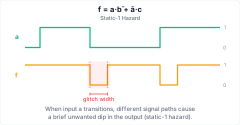
But the output should remain constant at each step. The hazard appears when we choose a configuration where f is constant at 1. Set b = 0, c = 1. Then f = a · 1 + ā · 1 = a + ā = 1 regardless of a.
Now trace a changing from 1 to 0 with b = 0, c = 1:
Initially a = 1:
- Gate 1 (computing
a · b̄): inputsa=1, b̄=1→ output 1. - Gate 2 (computing
ā · c): inputsā=0, c=1→ output 0. - OR gate: 1 + 0 →
f = 1. (Correct)
After a transitions to 0:
- The inverter producing
ātakes one gate delay to change from 0 to 1. - Meanwhile,
achanges to 0 immediately (from the external input). - Gate 1:
a=0, b̄=1→ output transitions from 1 to 0 after . - But Gate 2’s
āinput is still 0 (inverter hasn’t switched yet). So Gate 2 output = 0. - OR gate now has both inputs 0 → glitches to 0 briefly.
- One gate delay later,
ābecomes 1 → Gate 2 output rises to 1 → OR gate output returns to 1.
The output f briefly dips to 0 before recovering to 1. This is a static-1 hazard.
Why it happens
The hazard occurs because when a changes from 1 to 0:
- The path through the inverter + Gate 2 is longer (2 gate delays) than the direct path
ato Gate 1 (1 gate delay). - For one brief interval, neither product term is asserted: Gate 1 has already de-asserted, Gate 2 hasn’t yet asserted.
This is the fundamental cause of all static hazards: different path lengths cause a term to de-assert before its complementary term asserts.
Static-0 hazard
Dual situation in a POS circuit. For f = (a + b̄) · (ā + c), when b = 1 and c = 0, a change in a from 0 to 1 can cause a 0→1→0 glitch (static-0 hazard).
Dynamic hazards
A dynamic hazard occurs when the output should change (e.g., 0→1 or 1→0) but oscillates multiple times before settling.
Dynamic hazards arise in circuits with three or more levels of logic where multiple paths reconverge. The output transitions through a sequence: 0→1→0→1 (or 1→0→1→0) before settling to the correct final value.
Dynamic hazards are harder to analyse and fix. The typical approach is: eliminate all static hazards first, as dynamic hazards often arise from cascaded static hazards combined with unequal delays.
Timing diagram conventions
Logic signals on timing diagrams:
- Logic 1: top rail, labelled as such.
- Logic 0: bottom rail, labelled as such.
- Transitions: sloping lines reflecting finite rise/fall times.
A static-1 hazard appears as a narrow low pulse during what should be a constant high interval. The width of the glitch equals the difference in path delays (typically a few gate delays, i.e., nanoseconds).
Significance
In combinational logic feeding non-clocked inputs (e.g., an LED display), a glitch may be too fast to observe and harmless. In clocked sequential circuits, if a glitch occurs at a moment when a flip-flop is sampling the output (i.e., near the clock edge, violating setup/hold time), the circuit can enter a metastable or erroneous state. Hazard-free design is therefore important for reliable synchronous systems.