Logic Gates and Truth Tables
Logic Variables
Logic variables (also called binary variables or Boolean variables) can only take on two values. Different naming conventions are used interchangeably:
| Convention | Values |
|---|---|
| Boolean | TRUE, FALSE |
| Binary | 1, 0 |
| Voltage | HIGH, LOW |
| Switch | ON, OFF |
In electronic circuits these two values are represented by distinct voltage levels, e.g., a high voltage for logic 1 and a low voltage for logic 0. Using only two voltage levels gives digital circuits greater immunity to electrical noise compared with analogue circuits.
Logic Gates
A logic gate is a basic electronic circuit with one or more inputs and exactly one output. Gates are the atomic building blocks of all digital logic circuits. There are several ways to represent a logic function: a symbol (circuit diagram), a truth table (exhaustive input-output mapping), and a Boolean expression (algebraic form).
The NOT Gate (Inverter)
The NOT gate has one input and one output. Its output is the complement (inverse) of its input.
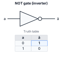
Truth table:
| a | y |
|---|---|
| 0 | 1 |
| 1 | 0 |
Boolean expression:
The circle (or “bubble”) on the output of the gate symbol indicates that the output is the complemented (inverted) version of the input. A NOT gate is also called an inverter.
The AND Gate
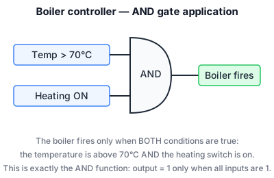
The AND gate output is TRUE only when all inputs are TRUE.
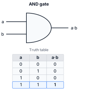
Truth table (2-input):
| a | b | y |
|---|---|---|
| 0 | 0 | 0 |
| 0 | 1 | 0 |
| 1 | 0 | 0 |
| 1 | 1 | 1 |
Boolean expression: (also written as , or )
The dot represents the AND operation. For multiple inputs, the AND operation extends naturally: ; the output is 1 only when every input is 1. A 3-input AND gate has 8 rows in its truth table, with only the row (1,1,1) yielding output 1.
The OR Gate
The OR gate output is TRUE when at least one input is TRUE (the inclusive OR).
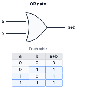
Truth table (2-input):
| a | b | y |
|---|---|---|
| 0 | 0 | 0 |
| 0 | 1 | 1 |
| 1 | 0 | 1 |
| 1 | 1 | 1 |
Boolean expression: (also written )
The plus sign represents the OR operation (not arithmetic addition). For multiple inputs: ; the output is 1 if any input is 1.
The XOR Gate (Exclusive OR)
The XOR gate output is TRUE when an odd number of inputs are TRUE. For two inputs, it is TRUE when exactly one input is TRUE (but not both).
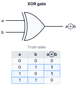
Truth table (2-input):
| a | b | y |
|---|---|---|
| 0 | 0 | 0 |
| 0 | 1 | 1 |
| 1 | 0 | 1 |
| 1 | 1 | 0 |
Boolean expression:
The XOR can be thought of as “a OR b but NOT both”, i.e., detecting inequality: iff .
The NAND Gate (NOT AND)
The NAND gate is an AND gate followed by a NOT. Its output is FALSE only when all inputs are TRUE.
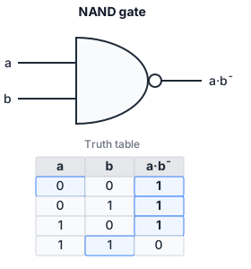
Truth table (2-input):
| a | b | y |
|---|---|---|
| 0 | 0 | 1 |
| 0 | 1 | 1 |
| 1 | 0 | 1 |
| 1 | 1 | 0 |
Boolean expression:
Equivalently, (by De Morgan’s theorem, see De Morgan’s Theorem). So y is TRUE if a is FALSE or b is FALSE (or both).
The NOR Gate (NOT OR)
The NOR gate is an OR gate followed by a NOT. Its output is TRUE only when all inputs are FALSE.
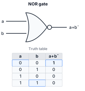
Truth table (2-input):
| a | b | y |
|---|---|---|
| 0 | 0 | 1 |
| 0 | 1 | 0 |
| 1 | 0 | 0 |
| 1 | 1 | 0 |
Boolean expression:
Equivalently, (by De Morgan’s theorem). So y is TRUE only if a is FALSE AND b is FALSE.
Universal Gates: NAND and NOR
Any Boolean function can be built using only NAND gates, or using only NOR gates. NAND and NOR are therefore called universal gates. This is important in practice because NAND and NOR gates are simpler to fabricate in many transistor technologies (particularly CMOS). The proof is straightforward: we can construct NOT, AND, and OR from NAND alone, and since {NOT, AND, OR} is functionally complete, NAND must be too.
Building NOT from NAND: tie both inputs together: .
Building AND from NAND: a NAND followed by a NOT (which is itself a NAND): .
Building OR from NAND: apply De Morgan: , which is a NAND of two complemented inputs (each complement is itself a NAND).
Similar constructions work for NOR.
Worked Example: Boiler Controller
Consider a heating boiler with the following inputs:
- : chimney is blocked (1 = blocked)
- : house is cold (1 = cold)
- : pilot light is lit (1 = lit)
- : overheat sensor triggered (1 = overheated)
Output : open the main fuel valve to start the boiler (1 = open).
The valve should open if and only if: the chimney is NOT blocked AND the house is cold AND the pilot light is lit, BUT NOT if the overheat sensor is triggered.
Boolean expression:
The circuit uses one NOT gate (for ), one NOT gate (for ), and one 4-input AND gate. If only 2-input AND gates are available, the three AND terms are cascaded: .
Combining Gates: Building
We will show how a more complex Boolean expression is implemented by connecting simpler gates. The expression involves NOT, AND, and OR operations. The circuit diagram consists of: input splits into two paths; one path goes through a NOT gate producing ; the other path goes together with into an OR gate producing ; the outputs of the NOT and OR gates are fed into an AND gate producing the final output .
Truth Table Construction
To build the truth table for this expression, evaluate it for every combination of the inputs and :
- List all input combinations: for inputs there are rows. Here , so 4 rows.
- For each row, compute intermediate sub-expressions.
- Combine sub-expressions to get the final output.
| a | b | |||
|---|---|---|---|---|
| 0 | 0 | 1 | 0 | |
| 0 | 1 | 1 | 1 | |
| 1 | 0 | 0 | 1 | |
| 1 | 1 | 0 | 1 |
So is 1 only when and . This is exactly , which can be verified algebraically:
This simplification shows that the OR gate (and the second path from ) was redundant. The truth table reveals this directly: the only row where corresponds to . This is a preview of Boolean algebra simplification, treated fully in the next note.
Gate-Level Equivalences via De Morgan
De Morgan’s theorem gives us important equivalences between gate types:
- An AND gate with bubbles on both inputs is equivalent to a NOR gate: .
- An OR gate with bubbles on both inputs is equivalent to a NAND gate: .
- An AND gate with a bubble on its output is a NAND gate.
- An OR gate with a bubble on its output is a NOR gate.
Two consecutive bubbles (complement operations) cancel: a bubble on an input followed by a bubble on the output of the same gate has no net logical effect. This “bubble pushing” technique is a practical method for converting between gate types and is explored in depth in the De Morgan’s Theorem note.